During conventional angiography, implanted stents can be hard to identify. In order to improve visualisation of metallic struts, stent enhancement (SE) algorithms have been developed.1 This technique, now available in most angiographic devices, works by identifying the two markers of a balloon positioned inside the stent, assuming that those markers move in synchrony with the metallic struts throughout the respiratory and cardiac cycle. Several frames from a cine loop, centred on the balloon’s markers, are then superimposed, thus providing a clear image of the stent.2 In order to get high-quality pictures, several technical expedients should be adopted:
- narrowing the field around the stent, keeping the device inside the window of view throughout the acquisition;
- ensuring that the balloon is not moving inside the stent;
- excluding other radiopaque structures from the field of view;
- putting the stent on a relatively radiolucent background, avoiding, if possible, the spine and the diaphragm (asking the patient to hold their breath may help to move the diaphragm away and minimise movement);
- positioning the C-arm perpendicular to the long axis of the stent, in order to minimise foreshortening; and
- obtaining two orthogonal views of the stent.
Originally, this method was developed in order to assess stent under-expansion; contrast can also be injected during stent enhancement imaging, which allows to identify a possible gap between the metallic struts and the vessel wall. Enhanced stent images can also be measured, provided that they are calibrated (generally by using the guiding catheter).3 Several small studies have compared SE to intravascular ultrasound (IVUS), observing a good correlation between the measurements obtained by these two different methods.2,4,5
However, in our current practice we do not perform SE imaging calibration routinely, as suboptimal stent expansion can be seen by visual estimation. The specificity of SE in identifying stent underexpansion is indeed comparable to IVUS; sensitivity is lower, ranging from 33–80%.6–8 We therefore perform SE routinely after stent implantation by using the markers of the delivery balloon; this quick and inexpensive manoeuvre often highlights stent under-expansion, which might otherwise go undetected based on simple angiographic images.7 SE is then useful during post-dilation, ensuring that the balloon is properly positioned inside the stent, and in assessing the result after high-pressure inflation.
Another setting where we very often use SE is implantation of overlapping stents.9 Indeed, stent overlap represents a risk factor for stent thrombosis, making it desirable to keep the area of overlay as short as possible. Just prior to implantation of the second stent we perform SE, which clearly shows the overlap; after implantation, we position the delivery balloon between the two stents, making sure that the area of overlap is appropriately expanded.
Besides these situations, SE can prove extremely useful in several other conditions;10 we present below three exemplary cases.
Case 1
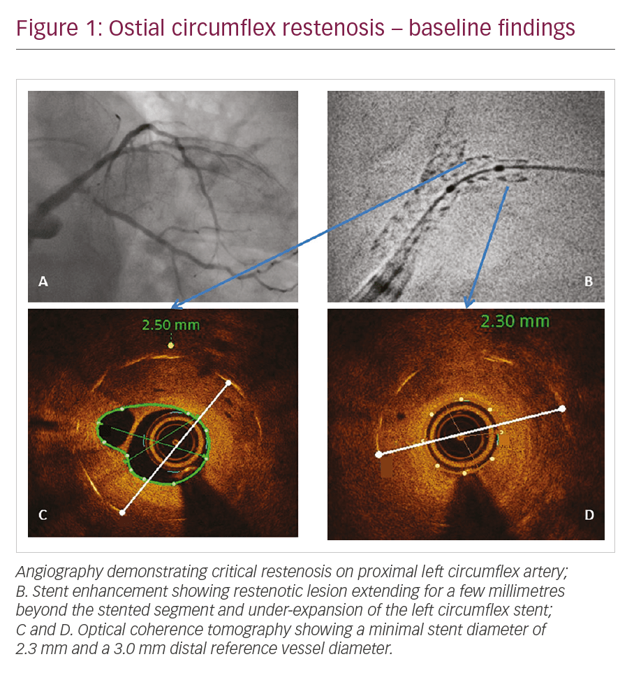
A 69-year-old female, treated 5 years prior with percutaneous coronary intervention (PCI) and implantation of two drug-eluting stents on left main (LM) bifurcation, presented with recurrence of angina. Angiography demonstrated critical restenosis on proximal left circumflex (LCx) artery (Figure 1A). SE was performed before stent dilatation in order to determine whether under-expansion was the possible causative mechanism. In very severe lesions, pre-dilatation with a small-sized, single marker balloon may be necessary before advancing a larger balloon with two markers. SE (Figure 1B) showed:
- the restenotic lesion involving the distal edge of the previously implanted stent, extending for a few millimetres beyond the stented segment; and
- the LCx stent appeared under-expanded, particularly in its distal part (where the critical restenosis occurred). This finding was best evidenced by optical coherence tomography (OCT), which showed a minimal stent diameter of 2.3 mm and a 3.0 mm distal reference vessel diameter (Figures 1C and 1D).
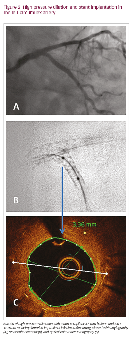
The lesion was treated with high-pressure dilatation with a non-compliant 3.5 mm balloon; another 3.0 x 12.0 mm stent was implanted in proximal LCx, sparing its ostium, with good result at angiography, SE and OCT (Figure 2).
Case 2
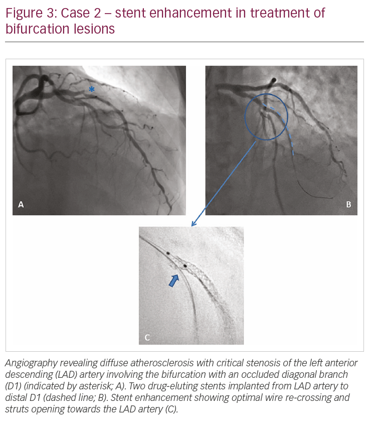
A 72-year-old male presented with angina and a positive stress test. Angiography revealed diffuse atherosclerosis with critical stenosis of the left anterior descending (LAD) artery, involving the bifurcation with an occluded diagonal branch (D1), and in the distal LAD artery (Figure 3A). The D1 was reopened with a Gaia® First (Asahi Intecc, Aichi, Japan) guidewire, and two drug-eluting stents (2.5 x 23.0 and 2.3 x 28.0 mm; XIENCE Sierra™, Abbott, Santa Clara, CA, USA) were implanted from the LAD artery to distal D1 (Figure 3B). The LAD artery–D1 bifurcation was treated with the culotte technique. After re-crossing stent struts with a workhorse wire towards the distal LAD artery, struts were opened with a 3 mm balloon; a first kissing balloon inflation was performed (with a 3.0 mm balloon on the LAD artery and 2.5 mm balloon on D1). SE performed at this stage clearly shows optimal wire re-crossing and struts opening towards the LAD artery (Figure 3C).
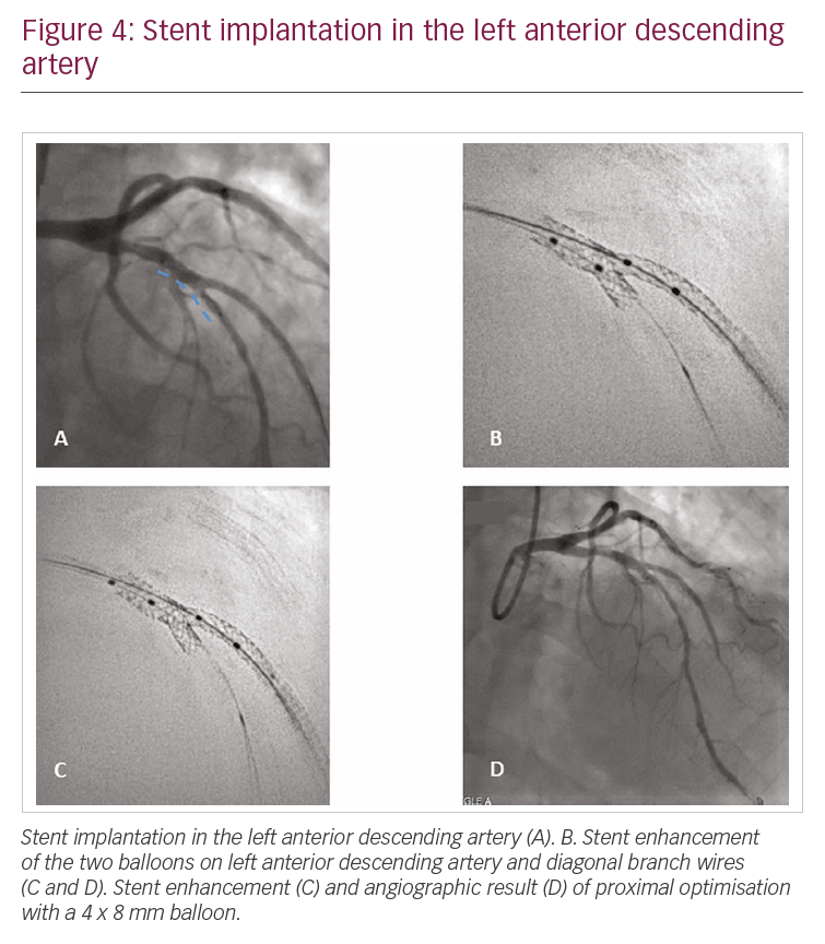
A further stent (Xience 3.5 x 15.0 mm) was then implanted in the LAD artery across the bifurcation (Figure 4A) and kissing balloon inflation was performed again. SE was repeated with the two balloons in the LAD artery and D1 wires (Figure 4B). Finally, proximal optimisation with a 4 x 8 mm balloon was performed. The angiographic results can been seen in Figure 4C and 4D.
Case 3
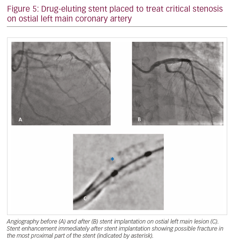
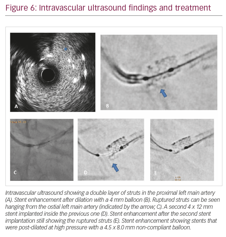
Case 3 refers to a 68-year-old gentleman presenting with critical stenosis on ostial LM coronary artery; the lesion was treated with implantation of a 4.0 x 12.0 mm drug-eluting stent (Figure 5A and 5B). SE immediately after stent implantation showed a possible fracture in the most proximal part of the stent (Figure 5C). IVUS evaluation was then performed (Figure 6A), showing a double layer of struts in the proximal LM artery, as if the stent was rushed. This explanation is, however, not plausible, as the guidewire had never been removed from inside the stent. The device was post-dilated with a 4 mm balloon; after dilatation, SE apparently showed ruptured struts hanging from ostial LM artery (Figure 6B). A second 4 x 12 mm stent was then implanted inside the previous one (Figure 6C), and still, the image at the LM ostium persisted (Figure 6D). The stents were then post-dilated at high pressure with a 4.5 x 8.0 mm non-compliant balloon (Figure 6E), with angiography and IVUS revealing good results (Figure 7).
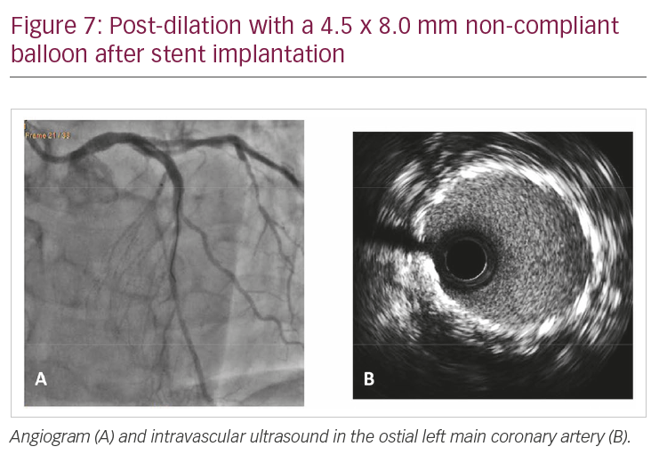
We do not have a clear explanation for the findings presented in this last case. It is possible that a connector in the proximal part of the stent broke, and that the disrupted struts were pushed inside the LM artery by the guiding catheter, giving the appearance of a crushed stent at IVUS.
Discussion
SE was originally developed as a mean to detect incorrect stent expansion; however, these three cases add to current literature highlighting its usefulness in settings as stent failure, bifurcation treatment and stent disruption.10–12 Of course, SE cannot replace intravascular imaging. The main limitation of SE compared to IVUS and OCT is that it only visualises stent struts, providing no information regarding vessel wall and plaque. Additionally, even if we focus on stent evaluation, intravascular imaging technology provides serial axial images of the implanted device, therefore not missing any eccentric defect; on the contrary, stent boost generally shows longitudinal reconstruction of the stent, which might miss under-expansion depending on the plane of acquisition. Obviously, no clues about edge dissection, plaque protrusion, thrombosis or residual disease at stent edges can be derived from SE, and all these are important determinants of immediate and long-term PCI results. Moreover, spatial resolution of intravascular imaging (OCT especially) is much higher than can be obtained with X-ray-based techniques. Finally, while the role of IVUS and OCT is clearly established by current literature and guidelines, use of SE is only supported by small studies and case series.13–16
On the other hand, it is a matter of fact that IVUS and OCT are, in most countries, largely underused.17 Several explanations can be provided, including cost (which in many countries is not reimbursed), additional procedural time, difficulty in image interpretation (particularly when IVUS is used), contrast requirement (for OCT) and high incidence of findings with uncertain clinical significance. Another factor potentially influencing the use of intravascular imaging is the operator’s confidence in immediate and long-term results of newer-generation stents.
Although often neglected, SE is instead a simple and quick tool that significantly improves stent visualisation, providing valuable information in several different settings.