The clinical introduction of cardiac electrophysiology (EP) studies in the 1980s was a cornerstone in how to understand, diagnose and treat specific arrhythmias. Anatomic orientation and positioning of catheters was achieved by fluoroscopic guidance. Signals were derived from intracardiac EP-catheters and interpretation of these, in combination with specific stimulation manoeuvres, led to successful therapies. Increasing complexity of procedures like pulmonary vein isolation (PVI) in atrial fibrillation (AF), ablation of ventricular tachycardia (VT) or complex atrial tachycardia (AT) have created a need for 3D-visualisation. This allows for a more precise insight into the arrhythmogenic substrate and reduces fluoroscopy in terms of creating a safer working environment for the physician and staff.
In 1999, single-point catheter-based mapping was first validated by Callans et al., using the CARTO® System in a porcine model of myocardial infarction, taking 75 endocardial mapping points.1 The electroanatomical map obviated the reliance on fluoroscopic substrate-based ablation within regions of low voltage and quickly became the central platform for scar-based VT procedures.
Various advanced electroanatomic catheter mapping systems (EAMS) are available today, each with specific strengths and weaknesses. The two most widely used systems are CARTO® 3 (Biosense-Webster, Irvine, CA, US) and EnSite™ NavX™ (St. Jude Medical, Saint Paul, MN, US). Common features of EAMS are the ability to localise at least one catheter in 3D-space, to create a 3D-map of the cardiac chambers of interest, to generate and display activation- and voltage-maps, and to tag sites of previous catheter positions or regions of interest (e.g., bundle of His, interesting potentials). The optimal mapping system for any patient depends on the character of the arrhythmia to be mapped and the operator’s familiarity within the system. Misinterpretation of the mapping data and improper data-acquisition or -processing are potential pitfalls associated with advanced EAMS.
Multielectrode catheters have been implemented routinely since the early 1990s2 for rapid diagnosis of supraventricular tachycardias using coronary sinus activation and in the anterolateral right atrium for cavotricuspid isthmus flutter.2 However, simultaneous acquisition of this electrical information into EAMS to define scar did not become popular throughout the early 2000s as the accuracy of these points remained in question because of variable tissue contact. The impedance-based electrofield system (EnSite NavX) was the first commercial mapping system that allowed for simultaneous voltage and activation acquisition from any catheter, regardless of model, make, configuration and electrode number. Patel et al. first demonstrated the use with a five-splined catheter (PentaRay®, Biosense Webster, Irvine, CA, US) to rapidly map left atrial flutters.3 In 2014, multielectrode mapping was implemented in a magnetically-based mapping system (CARTO 3) which allowed multiple points to be acquired very quickly, leading to colourful high-density (HD) maps due to less need for interpolation. This led to the challenge of developing automated algorithms to verify electrogram integrity and of differentiating between artefacts, noise and near- versus farfield determination.
Electrogram voltages are dependent on the electrode size and spacing, and the angle of the incoming wavefronts to the catheter.4 Consequently, standard scar-thresholds (e.g., 0.5–1.5 mV in VT ablation) need to be individualised for the new assortment of multielectrode catheters that are now available for several mapping systems.5 Modern catheters range from 10 electrode (e.g., Decapolar, Biosense Webster, Irvine, CA, US), to 16–20 (e.g., PentaRay and Lasso®, Biosense Webster, Irvine, CA, US; Duodecapolar/Lifewire™ and EnSite HD Grid, both St. Jude Medical, Saint Paul, MN, US) or even 64 electrodes (e.g., IntellaMap Orion™, Boston Scientific, Marlborough, MA, US). All these catheters have special characteristics which must be known in order to obtain an accurate map with precise information.
As Tschabrunn et al. demonstrated in 2016 in a porcine infarct-model, scar regions were 22% smaller with high density mapping with a multielectrode catheter (PentaRay 1 mm electrode size) as compared to the ablation catheter (3.5 mm electrode size), and greater tissue heterogeneity could be observed, allowing detection of remaining voltage channels in mixed scar areas and a greater ability to capture viable near-field tissue within dense scar.6 In the same year, the validation of an automated mapping system (Rhythmia HDx™ System, Boston Scientific, Marlborough, MA, US) with microelectrodes on a miniature basket catheter (IntellaMap Orion), was demonstrated in a porcine model with an average of more than 8,000 mapping points.7,8
Nowadays, most of the clinically relevant complex arrhythmias can be treated adequately or even be cured. For paroxysmal AF, PVI9 is a widely accepted therapeutic option10 as described in recent guidelines.11 For persistent AF, the results are less convincing, and the best strategy is yet unknown.12 Post-ablation ATs, propagating around scars of previous ablations, are often highly symptomatic for the patient, do not respond to antiarrhythmic drug treatment very well and are difficult to map and ablate during EP-procedures. Challenges here are significant low voltage areas (LVA), fractionated or multicomponent electrograms, difficult local timing annotation and often unreliable pacing manoeuvres due to high output pacing and lack of capture in LVA.13,14 Furthermore, electrogram amplitude and duration are influenced by electrode size and interelectrode spacing as mentioned above. Conventional mapping techniques such as activation mapping or entrainment manoeuvres can be challenging to interpret.
A precise visualisation of scars, isthmuses and gaps seems to be crucial for a successful ablation, suggesting the need for HD mapping for complex arrhythmias, especially complex AT. Specialised multielectrode catheters are available for standard EAMS, such as CARTO 3, EnSite NavX and the novel Rhythmia HDx mapping system. The use of an 3D-EAMS can facilitate mapping and guide ablation.15 (Ultra) HD mapping in AT can reveal underlying structures and activation patterns, and can help categorise AT as macroreentry, microreentry or true focal AT. A recent publication by Schaefer et al. described initial experience with the Rhythmia™ System using an expandable, open irrigated 64-polar mini basket catheter (Orion™, Boston Scientific) consisting of eight splines with eight electrodes each and a spacing of 2.5 mm providing a very small electrode surface area of 0.4 mm² and an open irrigated 3.5 mm tip mapping and ablation catheter (Thermocool™, Boston Scientific, Marlborough, MA, US).16 The basket catheter was used to create an ultra-HD electroanatomical model of the right and/or left atrium. All data were acquired during AT and electrogram-annotation was performed automatically by the mapping system. Based on this, the AT-mechanism was determined by distinguishing macroreentry from non-macroreentry AT. Areas of earliest activation, areas of slow conduction and isthmus areas could be determined in all cases.16 In a study by Kapa et al., a voltage of 0.2–0.45 mV was chosen for scar mapping.17 Consequently, areas considered critical for the AT initiation or maintenance were mapped with the ablation catheter. Mean mapping time was below 20 minutes and the mean number of mapping points automatically acquired was almost 20,000. A high accuracy of the generated maps was confirmed by left atrial angiography. Acute outcome showed non-inducibility in all patients. The authors concluded that such HD-maps mean a deeper understanding and more precise characterisation of complex tachyarrhythmias, which is essential for AT-Mapping. They suggested that ultra HD mapping may harbour the potential to allocate valuable information regarding further AT by a single map to minimise repeat mapping time.17 Settings to define scar were derived from a previous study,16 leading to discussions about how the scar threshold would be influenced by using a mini-basket catheter with very small inter-electrode spacing and small electrode-size. Thus, further investigations in optimal settings for the Rhythmia System’s scar-identification seem necessary.
A study by Anter et al. also evaluated the Rhythmia mapping system for ablation of scar-related ATs.18 Only patients with recurrent AT within 2 years of previously failed ablation procedure were included. In all previous procedures the arrhythmia had not been able to be adequately mapped and was ultimately terminated with empiric ablation lines or electrical cardioversion. Again, activation maps included a huge number of electrograms (>12,000 versus 576±314 in the previous procedure) acquired within an average of 25 minutes. Rhythmia showed a similar LVA; however, the activation map was able to define the mechanism and location of the circuit in all 14 cases and revealed a macroreentrant circuit in five patients with previously failed ablation of an assumed “focal” tachycardia. The authors concluded that this new type of mapping offers several potential advantages for mapping scar-related ATs and highlighted the importance of mapping resolution, integration of unipolar electrograms and algorithms to determine map coherence.18
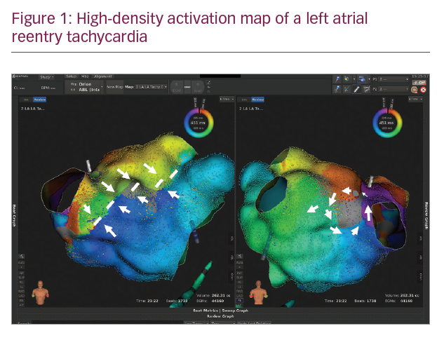
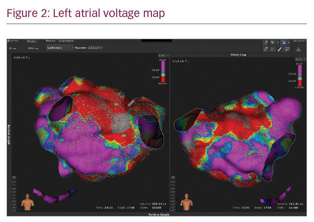
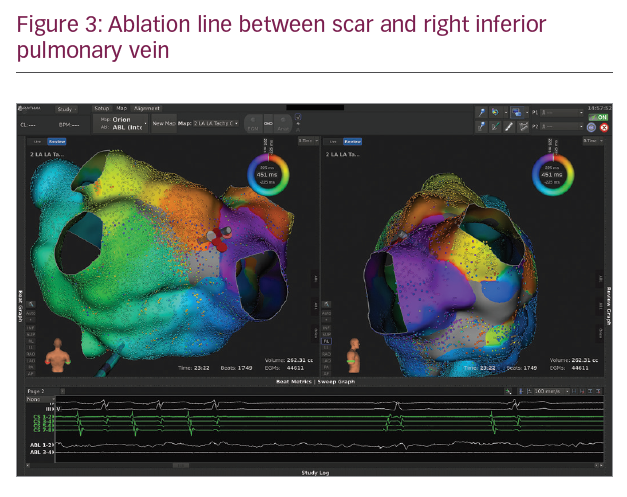
In Figures 1–3 we present a case of our own series using the Rhythmia system. A 53-year-old male patient with a history of mitral valve repair and ablation of a multifocal AT presented with incessant AT. Figure 1 shows the HD activation map of a macroreentrant left atrial reentry tachycardia consisting of >44,000 electrograms acquired. Reentrant activation is present around a scar area close to the right inferior pulmonary vein and a pre-existing block line is detected at the roof. The voltage map (Figure 2) shows pre-existing large areas of low voltage (red) and scar (grey) comprising the whole left atrium. An ablation line connecting the scar area with the right inferior pulmonary vein terminated the tachycardia (Figure 3) and rendered it non-inducible.
Regarding ablation of VT in ischemic cardiomyopathy, Tschabrunn et al. compared voltage distribution and electrogram characteristics of a multielectrode-mapping catheter (PentaRay) versus a standard ablation catheter (Thermocool) in the ventricle of post-infarction and healthy swine.7 Their major findings were:
- a similar bipolar voltage amplitude between both catheters in a healthy tissue (~1.5 mV);
- an enhanced mapping resolution within areas of low voltage with multielectrode catheters, identifying channels where otherwise dense scar was considered;
- the superiority of multipolar catheters for mapping scar-related reentrant VT because of closely spaced electrodes, allowing identification of distinct diastolic activity; and
- the possibility of pacing with lower output within low-voltage-tissue compared to linear catheters.
They summarised that, in comparison to healthy tissue, where there was no benefit of a higher mapping resolution, the biggest advantage of multielectrode catheters for HD mapping lies in detecting channels and isthmuses in ventricular scar-areas.7
To conclude, (ultra) HD mapping seems to be a potentially powerful tool to understand macro- and microreentrant tachycardias and to detect critical ablation sites – a key to successful ablations – where standard catheters failed to show adequate signals in previous procedures. These benefits mainly arise from a small electrode size, narrow inter-electrode-spacing and ability to record the activation vector and angle of incidence during tachycardias. This results in HD, high-resolution maps, consisting of several thousand points of interest with only little need for artificial interpolation in comparison to low-resolution maps. Smart algorithms allow a straightforward workflow with fast map-acquisition and parallel interpretation of signals. Variations in interelectrode spacing necessitates tailored bipolar thresholds to optimal scar detection.19 The choice of system, catheter and filter-settings combination depends on personal preferences and experience. It is essential to understand the benefits and pitfalls of each HD-mapping system in order to achieve ablation success during EP studies.
As no randomised, controlled trials on the possible benefits of HD mapping over standard 3D mapping with lower resolution has been published so far, further studies are clearly needed to elucidate the potential value in different arrhythmia substrates.