Ventricular tachycardia (VT) ablation presents a challenging and growing area of focus in the realm of complex ablation, with promises of improved patient’s quality of life and clinical outcomes.1,2 Classic approaches to VT ablation centered on arrhythmia induction and entrainment of the circuit in order to identify the components critical to arrhythmia propagation. Identification of mid-diastolic potentials in the critical isthmus and ablation with termination of tachycardia represent the mainstay of this approach.3 Activation mapping has been consider and taught to be the gold standard of targeted VT ablation in the past but is not always a feasible approach in unstable tachycardia, typically leaving the less precise option of substrate-based ablation. High-density (HD) mapping and functional substrate characterization approaches have evolved which allow more precise targeting of un-mappable VT and carry with them the promise of improving patient outcomes in this complex population.1
Challenges of classic ventricular tachycardia ablation
Ventricular tachycardia circuits rely on defined functional components necessary to initiate and propagate reentrant tachycardia, and successful termination of these circuits relies on identifying these components. At its most basic, a VT circuit requires areas of conduction block, an entrance into a corridor between these areas of conduction block, and an exit back into the remainder of viable myocardium.4 These elements are termed the entrance, isthmus, exit and outer loop. Further functional elements are also required, including an area with potential for unidirectional block and areas of slow conduction which allow for impulse propagation and reentry within the circuit. This ‘functional’ role refers to dynamic tissue characteristics not directly attributable to voltage or scar, but rather its ability to conduct wavefronts at various speeds, in various directions or at various coupling intervals. While the simplest of circuits can propagate VT with an entrance, isthmus, exit and outer loop between two areas of scar, most VT circuits are more complex with multiple exits with potential for functional block and remote and adjacent bystander tissue not critical to the circuit.5 Ablation of non-critical components of a VT circuit, such as the outer loop or bystander components or sites of multiple exits, are unlikely to lead to clinical success, wherein lies the challenge in successful VT ablation.4
With the advent of coronary reperfusion therapy in the form of percutaneous intervention, the ischaemic cardiac substrate and subsequently, the face of VT ablation, has changed. While preserving greater territories in the setting of acute myocardial infarction, reperfusion has also led to smaller areas of dense scar tissue, larger peri-infarct zones and increased areas of patchy and heterogeneous scar tissue. In the setting of VT, this has led to generally shorter VT cycle lengths, which often lead to more haemodynamic instability with arrhythmia induction.6 Rates of haemodynamic instability with induced VT can be as high as 50–90% during ablation procedures, with greater than 60% of cases having un-mappable VTs. Furthermore, VT can be non-inducible in up to 14% of patients at time of electrophysiology study and ablation, and often the true clinical VT as defined by 12-lead-EKG may not be known or available.7,8 While targeted induction, entrainment and ablation of clinical VT may be the classically preferred approach, the reality remains that this is often not feasible in the majority of cases that present to the electrophysiology lab. The remaining options for VT ablation in the setting of unstable arrhythmia centre largely on substrate-based ablation and mechanical circulatory support of unstable VT mapping. While the latter has provided a means of ablating unstable VT, it has been shown to do so at the cost of longer procedure times and increased number of inducible VTs, some possibly non-clinical, to be ablated compared with substrate-based approaches.9
Substrate ventricular tachycardia ablation approaches
Substrate-based approaches do not rely on the classic methods of arrhythmia induction, entrainment and target ablation, and rather focus on homogenizing scar areas likely to support arrhythmia circuits. VT ablation is a complex and involved procedure requiring preoperative planning and ideally, identification of clinical VT circuits based on a 12-lead electrocardiogram (ECG) and the exit site of the VT circuit. If a 12-lead ECG is not available for the clinical VT, as is often the case, intracardiac recordings from implantable cardiac defibrillators frequently provide some correlation with clinical target VT in the form of far-field and near-field electrograms.10 Preoperative cardiac magnetic resonance imaging (CMR) or cardiac computed tomography (CCT) can provide the location of the myocardial scar. Combining this information often informs both the planning of classic activation-based and substrate-based approaches to VT ablation, and provides a starting point for the invasive portion of the VT ablation procedure. Once a VT has been determined upon invasive approach to be haemodynamically or electrically unstable enough to prohibit circuit mapping and definition, a substrate-based approach is the only remaining option. Several groups have demonstrated that substrate-based approaches can provide similar efficacy in eliminating clinical VT circuits, as well as reducing the number of recurrent non-clinical VTs, as opposed to more targeted mapping approaches.10,11 With comparable or even superior success, and the increasingly common occurrence of un-mappable VT, further improving upon substrate VT ablation carries the promise of meaningful clinical benefit for patients.1,2
Established methods of substrate-based ablation have generally focused on eliminating arrhythmic circuits identified by voltage mapping without clearly establishing their role or potential in putative clinical VTs. Voltage mapping leads to identification of areas of dense and heterogeneous scar tissue and marginal zones which can serve as components of the VT circuit. Linear substrate ablation is one approach that involves connecting electrically inert structures by administering radiofrequency ablation to complete lines across target areas. The goal of these lines is to transect and disrupt the heterogenous voltage or borderline scar tissue with potential for slow conduction and critical VT isthmuses.12 Linear ablation was shown in one study to provide up to 65% reduction in recurrent VT at 12 months.12
Another approach involves identification of conductive channels of viable voltage through dense scar tissue and the targeting of those channels which may have potential of serving as the critical isthmus in arrhythmia.13 Core or substrate isolation has been identified as a potential method of isolating areas of homogenous scar tissue by performing boundary isolation of the homogenous tissue, with some analogy to pulmonary vein isolation.14,15 Scar homogenization approaches aim to identify any area of marginal or heterogenous scar tissue and convert it to dense scar tissue, thereby reducing its ability to propagate VT. These approaches have shown efficacy and are largely independent of any functional assessment of the tissue or its actual involvement in clinical VT.10
Signal-based substrate approaches
Several substrate-based approaches incorporate concepts of functional properties of abnormal tissue propagation to allow target ablation in un-mappable VT. Conducting channel identification and voltage adjustment approaches seek to identify channels in scar tissue by their ability to conduct to surrounding tissue, thereby establishing their potential role in VT propagation. Split potentials (separated by 30 ms isoelectric periods), local abnormal ventricular activation (LAVA) characterized by low voltage (<3 mV) or long activation (>70 ms) and late-potential (LP) (>30–50 ms post QRS) mapping seek to find areas of abnormal potential or late activation (Figure 1e). These signals have shown potential for involvement in a diastolic or slow conducting corridor critical to VT propagation, but are nonspecific findings.16 While the presence of LAVA suggests slow conducting tissue and LPs show tissue that may be activated in a delayed fashion leading to potential reentry, they also do not clearly declare their role in any undefined VT circuit, and elimination of these potentials as a procedural endpoint can involve substantial ablation delivery without defined functional contribution of the targeted substrate.17
Figure 1: Substrate Based Mapping Approaches
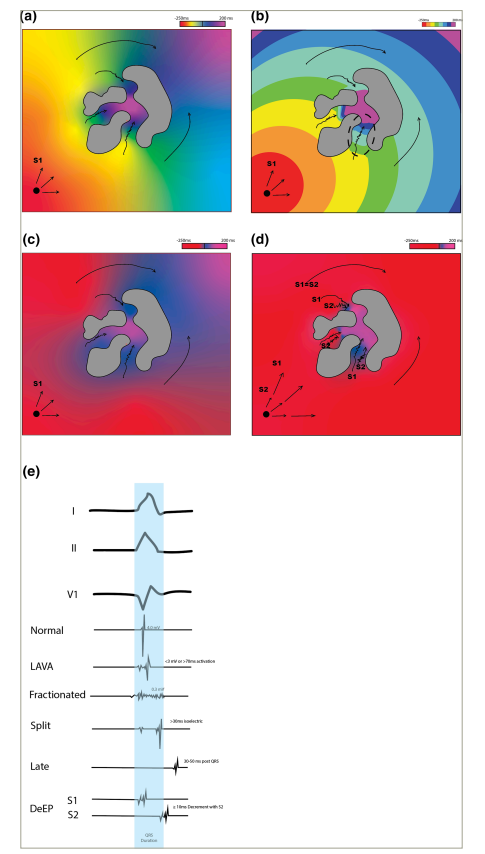
Schematic representation of: (a) Local activation map with late activation noted within scar (grey). (b) ILAM map with activation divided into equal octiles of paced cycle length. Dotted circle shows area of ILAM crowding. Note that difficulty with interpretation can arise with interpolation of colour and lines of functional block (*). (c) Late potential mapping. (d) DeEP mapping with only potentials that show greater than 10 ms decrement with S2 pacing being annotated as late potentials. (e) Example of signal types.
DeEP = decremental evoked potential; ILAM = isochronal late activation mapping; LAVA = local abnormal ventricular activation; S1 = stimulation 1; S2 = stimulation 2.
High-density substrate ablation
HD mapping technology has brought with it the promise of targeted substrate ablation due to improved functional substrate and voltage characterization. Mapping catheter design has advanced rapidly in terms of electrode size and inter-electrode space diminution, as well as spatial orientation designs meant to maximize local voltage fidelity and, as a result, improved tissue characterization (Figure 2).18 HD multi-electrode catheters (HD MEC) such as the HD Grid™ (Abbott Cardiovascular Inc., Abbott Park, IL, USA), Optrell™ (Biosense Webster Inc., Irving, CA, USA), Octaray™ (Biosense Webster Inc., Irving, CA, USA) and Orion™ (Boston Scientific, Inc, Cambridge, MA, USA) catheters to name a few, have allowed more point collection, point density and point discrimination than other generation linear or focal mapping catheters. HD MECS allow for better specificity of true dense scar tissue, identification of finer abnormal signals and bands of surviving conductive myocardium, better definition of low voltage signals and lower output pacing capture.18 HD MECs also often provide multiple vector wavefront signals which have the potential to overcome what has been termed ‘perpendicular blindness’, which may lead to voltage underestimation, depending on the linear alignment of lower density catheters with relation to voltage propagation.19,20 HD MECs allow for better signal definition, identification of abnormal conductive areas and multipolar directional assessment of local conduction.21 As a result, components of a VT circuit such as areas of slow conduction, late activation conduction block and critical conductive channels can be identified even without activation mapping and entrainment in tachycardia. LAVAs or fractionated potentials may be identified as possible slow conduction entrance zones or exit zones, late or split potentials as possible diastolic corridors or blind loops, while other long fractionated signals may be nothing more than remote bystanders with no potential role in clinical tachycardia.
Figure 2: Voltage mapping with standard versus HD MEC
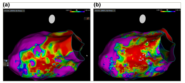
(a) VT voltage mapping using a linear multi-electrode catheter (Decanav™, Biosense Webster Inc., Irving, CA, USA) 1 mm electrode at 2-8-2 mm inter-electrode spacing. (b) Multi-electrode grid shaped HD mapping catheter (Optrell™, Biosense Webster Inc., Irving, CA, USA) showing increased areas of marginal voltage allowing more specific targeting of possible conductive channels for VT. Voltage range selected to show increased fidelity of marginal zone with HD versus standard catheter.
HD = high density; MEC = multi-electrode catheter; VT = ventricular tachycardia.
High-density functional mapping approaches
Newer substrate-based approaches have sought to establish the potential functional components of VT circuits without the necessity of stable arrhythmia. Isochronal late activation mapping (ILAM) involves activation mapping during sinus or directional-paced rhythm with even division of local activation time (LAT) annotation into octiles which are colour coded (Figure 3). This method of activation mapping visually assigns a uniform time of conduction across varied areas of myocardial tissue. Areas of isochronal crowding characterized as more than three isochrones in an area of less than 1 cm radius, representing at least 3/8th (37.5%) of the total ventricular activation time, have been shown to correlate with areas of slow conduction consistent with critical sites required for VT propagation.22 Limitations to the ILAM approach include a lack of automation for some mapping systems, inability to identify lines of local block posing as deceleration zones and artifact introduced by interpolation. This approach attempts to show the functional basis for mapping VT circuits in a voltage-independent manner with potential for more efficient targeted ablation, with one study showing up to 70% freedom from VT at 12 months using this targeted substrate-based approach. 23,24
Figure 3: Isochronal Targeted Substrate Ablation
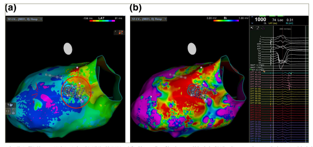
(a) HD mapping (Optrell™, Biosense Webster, Irving, CA, USA) with ILAM on left with crowding of isochrones within circle. (b) HD voltage mapping; note the late potentials during paced rhythm corresponding to potential corridor under the mapping catheter. Ablation here led to non-inducibility of clinical VT.
ILAM = isochronal late activation mapping; HD = high density; VT = ventricular tachycardia.
A second functional approach to substrate mapping termed ‘decremental evoked potential’ (DeEP) mapping involves a refinement of LP mapping with examination of those potentials which show decrement with ventricular extra-stimulus.25,26 The concept of DeEP mapping centers on the principle that VT circuits rely on the critical components of slow conduction and unidirectional block to initiate and propagate tachycardia with an induced excitable gap that supports reentry (Figure 1d).25,26 By mapping areas with potentials decremented by at least 10 ms with ventricular single extra-stimuli, Bhaskaran et. al. suggested that they can bring more specific elucidation to a substrate, with the ability to induce slow conduction and allow for reentry.26 Like the ILAM targeted technique, ablation using DeEP mapping to further specify substrate with potential for VT circuit propagation has led to very positive post-intervention outcomes, with as many as 75% of patients free of VT at 6 months follow-up.27,28 Use of these aforementioned techniques have been shown to further inform mapping strategies for more targeted substrate ablation when stable mapping is not possible.24,27,28 DeEP mapping does involve manual annotation of evoked potentials without the automated annotation available on current mapping systems. With targeted ablation, elimination of all LP and LAVA may not be necessary, with studies involving these targeted methods showing comparable clinical efficacy with reduction in the extent of tissue needing ablation.12,17,24,28
By combining voltage and functional substrate mapping approaches with HD mapping tools, a hybrid functional and targeted ablation approach becomes possible, even in settings of unstable tachycardia. HD mapping provides fine signal and voltage delineation showing possible putative conductive channels, areas of LAVA and late activation during sinus or ventricular-paced rhythm. Identification of isochronal crowding suggests an area of slow conduction, which may further give direction to a region of abnormal tissue critical to the ventricular arrhythmia. DeEP mapping may also solidify components of abnormal tissue as having a role in the reentry circuit consistent with the clinical unstable tachycardia. Once elements of abnormal tissue properties in areas of slow conduction consistent with possible VT circuits have been identified, pace mapping can be used to further identify possible circuit exit points or even conductive channels (Figure 4). At times, these approaches can be combined to provide targeted activation mapping of the diastolic corridor in even unstable VT, if only for a few beats. Using careful substrate characterization and functional analysis combined with anatomical correlation, targeted ablation can be carried out with great success even in unmappable tachycardias.
Figure 4: Correlation of voltage mapping, ILAM and pace-mapping sites with successful ablation
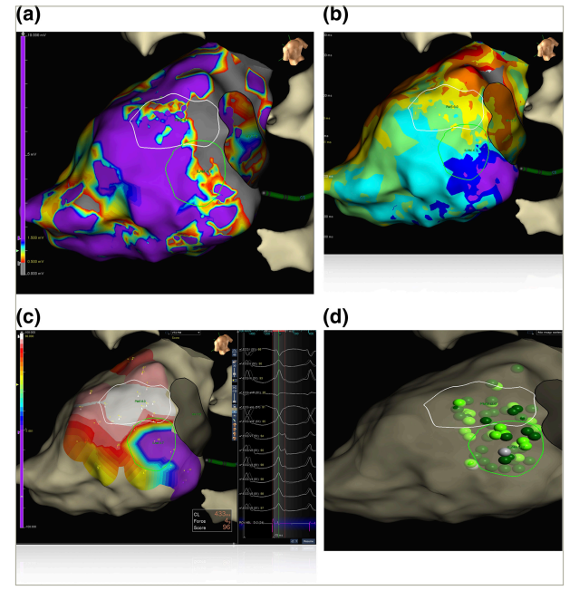
a) Voltage mapping (b) ILAM on left with crowding of isochrones within circle. (c) Pace-mapping from ablation catheter showing exit sites with high percentage match in white. (d) Ablation of ILAM–indicated corridor led to non-inducibility of VT.
ILAM = isochronal late activation mapping; VT = ventricular tachycardia.
Imaging-based substrate mapping
Preoperative noninvasive imaging continues to evolve, with promise of improving procedural efficiency and outcomes in HD approaches to substrate VT ablation.29 Multimodality imaging such as CMR has long been able to identify areas of myocardial scar or thinning suggestive of substrate responsible for VT circuits.30 CMR-identified putative conducting circuits have been shown with substrate mapping to correlate with functional-based ILAM mapping in the identification of VT circuits.31 New advances in molecular CMR approaches analyze variable contrast uptake in marginal tissues and may be able to provide more subtle assessment of potential isthmus zones and VT circuits.32 CCT techniques have evolved and allow for continually improving wall thickness analysis which may provide much of the same information previously gained through CMR.33,34 As the field evolves, computer-based models are beginning to develop predictive algorithms for potential functional circuits based on scar mapping.35 Utilizing this advanced imaging and the growing number of noninvasive techniques for substrate assessment and even potential functional mapping will assist in invasive approaches, and can provide a framework for successful ablation, even in unstable VT.
Discussion
By bringing together multiple approaches of preoperative planning, substrate imaging and intra-procedural functional substrate mapping, unstable VT can be more safely and effectively ablated in a targeted fashion (Figure 5). Prior to the procedure, advanced substrate imaging provided by CCT or CMR will inform plausible substrate targets. This information can be correlated with the surface ECG of the clinical VT if available or with intracardiac device tracings upon induction. Upon induction of the VT, if it is haemodynamically tolerated, mapping and ablation in tachycardia can be carried out in the classic fashion. If not, then a substrate-based approach should be pursued. HD voltage mapping of substrate targeted to baseline imaging and VT morphology should be carried out. Notation of LAVA and LP during mapping will help annotate areas of abnormal tissue and can be correlated with imaging as well. Functional mapping such as ILAM can further delineate areas that may represent slowing with contribution to the reentry circuit. Pace mapping, once the putative circuit is identified, can further narrow the focus of target ablation. Once the area of a functional corridor has been mapped with these techniques, it is possible to re-induce and attempt limited mapping of a diastolic corridor, if only for a few seconds before haemodynamics are compromised. Ablation can be carried out after this targeted mapping. Once LP and LAVAs in the targeted zones of interest are attenuated to dense scar tissue, re-induction should be reattempted. Elimination of all LPs may not be feasible due to the extent of abnormal tissue in many cases. This approach should be continued until no clinical VT is inducible with a standard ventricular stimulation protocol. At times targeted ablation can slow but not terminate the VT circuit, making previously unstable tachycardia mappable. By using these methods, unstable VT can be more safely and effectively targeted with a HD substrate ablative approach.
Figure 5: Workflow for HD approach for unstable VT ablation
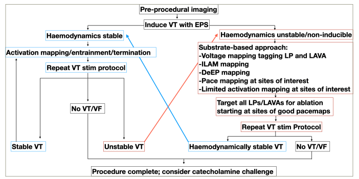
Unstable VT may be stabilized by targeted ablation but not terminated, allowing for classic approach of mapping and entrainment
DeEP = decremental evoked potential mapping; EPS = electrophysiology study; ILAM = isochronal late activation mapping; LAVA = local abnormal ventricular activation; LP = late-potential; VF = ventricular fibrillation; VT = ventricular tachycardia.
Conclusion
VT ablation has proven to be a challenging procedure which carries great potential benefit for patients. Unstable VT, increasingly common in the post coronary reperfusion era, poses a particular challenge for ablation. By utilizing a tailored HD mapping-guided substrate-based approach with consideration of functional tissue properties, this complex arrhythmia may be safely and successfully ablated.

